Euri Gilberto Herasme Cuevas
Euri Gilberto Herasme Cuevas
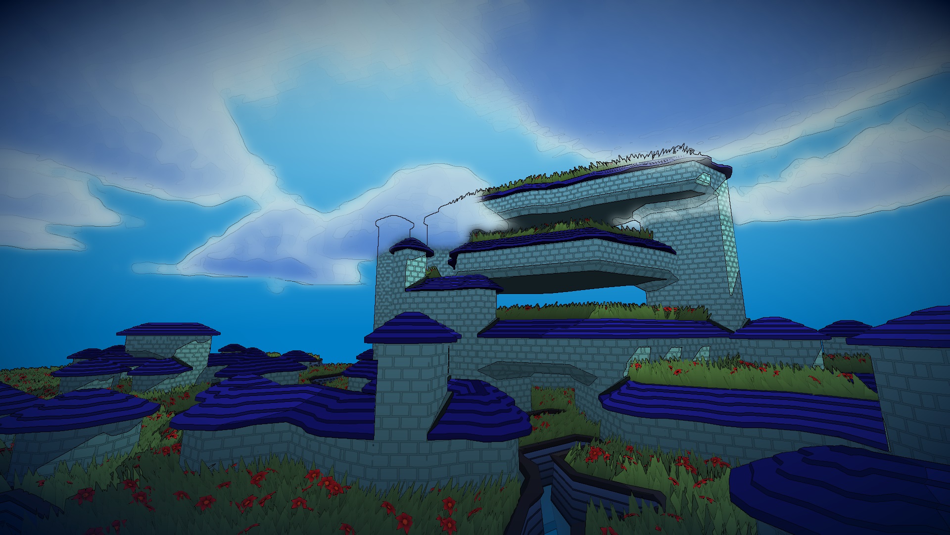
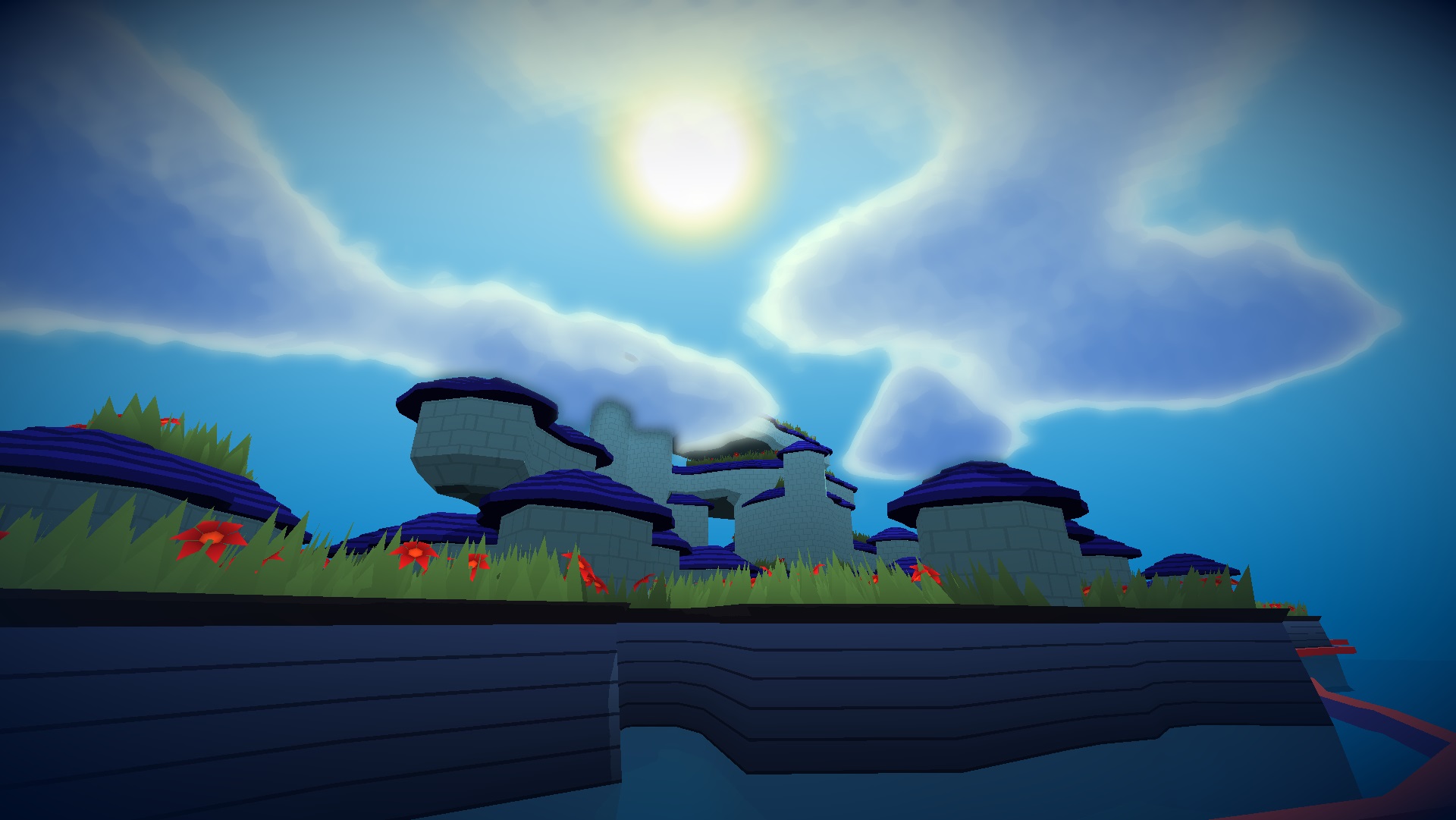
Tower Builder
Hello everyone! I have been working on a Tower Building toy game on the web inspired the awesome Townscaper by @OskSta . Volumetric clouds based on @SebastianLague explanation. It was made entirely with JavaScript using Threejs for 3d and PixiJS for 2d. It is also my submission to the Tech Art challenge by @HarryAlisavakis 's discord channel #TechnicallyAChallenge for the themes Flowers and Procedural Generation.
JS
ThreeJS
PixiJS
GLSL
Available Here!
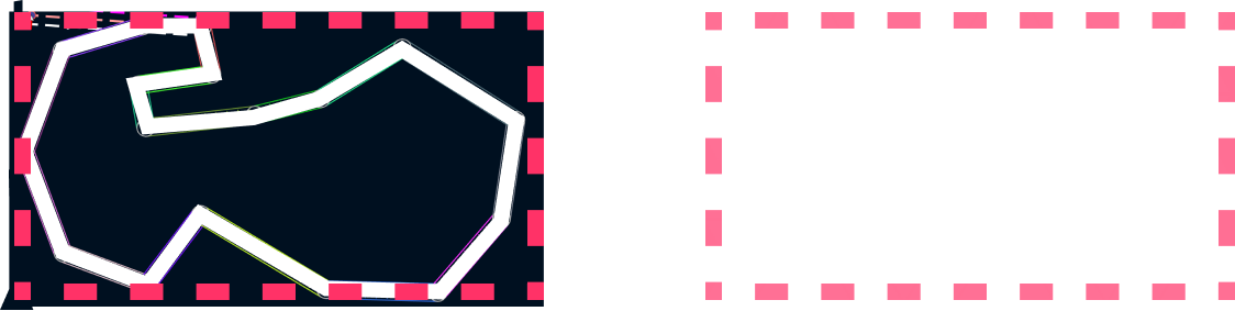
Step 1
The user generates a 2d polygon with non intersecting edges. The
current version of the system is using rotated bounding boxes to
stop the users from having crossing lines (it currently breaks on
the vertices, because I have not added a circle to the bounding box
intersection yet).
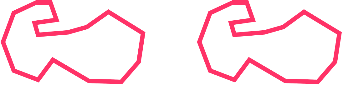
Step 2
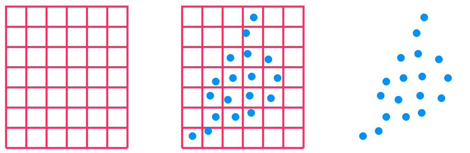
I create a grid of equilateral triangles using the axis aligned
bounding box that contains the generated polygon.
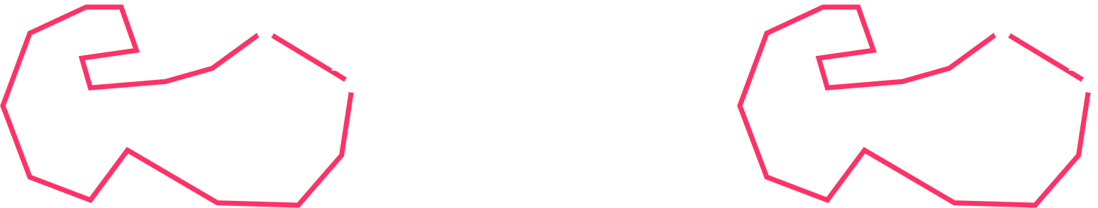
Step 3
Remove all the triangles that do not have all their vertices inside
the polygon defined by the user. To do this I use the winding number
of each vertex and the polygon.
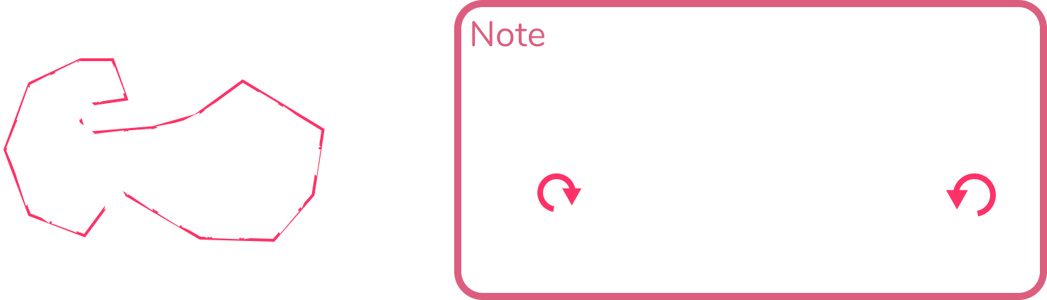
Step 4
Now that all the vertices are inside the shape, move all outer
vertices (vertices that are part of edges with only one connected
triangle) into the edges of the polygon. To do this I first compute
the “normal” of each edge, computed doing the cross product between
the normalized “edge vector” and (0, 0, 1).
This is only true if the polygon is in clockwise order, which might
not be true because it is generated by the user, so they could
easily make it clockwise or not. To ensure it is clockwise, after
the user closes the shape, I check if the vertices are in clockwise
order and if they are not I invert the orther.
This ray to edge intersection is done with each outer vertex for
each of the edges. Then for each vertex the list of collisions is
sorted in ascending order from closest edge to farthest edge (if the
computed distance is 2 times the edge length used for the triangles
in the triangular grid then it is discarded).
The edges are only moved if doing so would not change the order of
the vertices of the triangles it is connected to. This ensures the
vertex is not creating overlapping edges without having to test
every edge against everty other edge.
Step 5
For each vertex in the original polygon move the closest outer
vertex to it, and follow the previous rule of only moving the
vertices if the movement would not change the order of the vertices
in the triangles.
Step 6
After the previous step, I collapse some of the outer edges that are
too short (which removes the triangle that had the edge, and removes
a single vertex).
Step 7
Randomly collapse edges that do not have an outer vertex. The edges
to collapse should be part of triangles that are not too deformed,
and the collapse should also avoid the creation of a vertex that is
connected to only 3, 4, or more than 8 triangles.
Step 8
Remove “problematic” vertices or triangle combinations. These
problematic elements are some of the things that seem to lead to
undesirable results. With remove I mean, collapse some edge that
would remove it. The configurations are:
Step 9
Triangle relaxation. This is based on Oskar Stålberg's quad
relaxation algorithm but applied to triangles. In this case I want
to ensure that all the edges of the triangles are the same length,
to achive this I do the following.
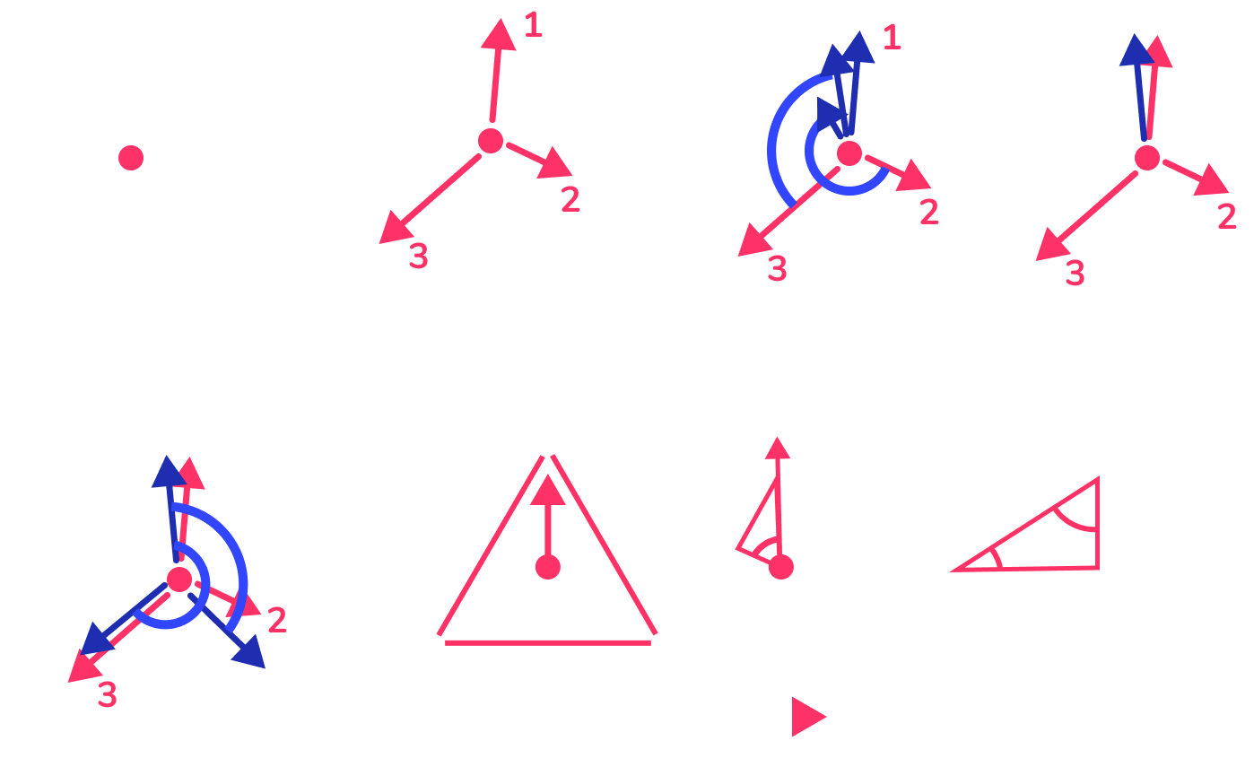
1
Get the center
2
Get vector form the center to the vertex of the triangle, and number the vectors
3
Rotate clockwise the vector 2, 240 degrees, and vector 3, 120 degrees. (this is done because that would be the separation between the 2nd and 3rd vector in an equilateral triangle) then average them.
4
Scale the average vector to the legnth the vector would have if it was an equilateral triangle with the edge length provided. (not scaling it properly would lead to the triangles getting smaller). Create 2 rotated vectors from the resulting average vector, for the vertex 2 the vector should be rotated 120 degrees and for the vertex 3 it should be rotated 240 degrees.
5
Then compute the difference between the new position and the position it had before, and that gets you the movement needed for each vector to create an equilateral triangle. This is done for each triangle, and for each vertex all the movement vectors are added and applied at the end.
Step 10
While the figure is being relaxed, I also remove some of the more
deformed triangles. Every N time step I make an array with the
“most” deformed triangles and collapse a couple (it's a magic
number, it does not have any particular meaning) of the smallest
edges, and I do the same thing for the outer edges (in a separate
step).
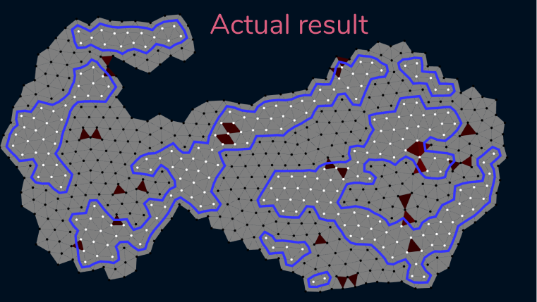
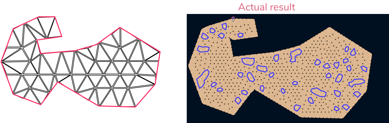
The red, green and grey triangles are a debugging view. If the
triangle is “more” deformed because its area is bigger / smaller
than intended then it is red, if it is “more” deformed its minimun
internal angle is too small then it is green, and the color
intensity relates to the intensity of the deformation.
The blue lines are a marching “Triangles” algorithm running and the
dots were painted black or white depending on their normalized
position in the polygon bounding box. That position is fed to a
perlin noise I generate each time the sytem starts (you can see it
on the fourth quadrant, pan down).
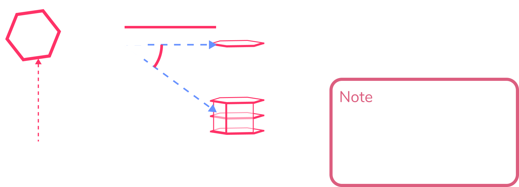
For the 3d space I am using a marching “triangular prism” algorithm,
it is basically the same as the marching cubes algorithm but for
triangles. The vertices of the prism can be in one of 3 states:
water, tower or air. When the system starts, the vertices on the
first layer are all water, and all the other vertices are air. When
the user clicks to add a node the hovered vertex changes state from
‘water’ / ‘air’ to ‘tower’ and the marching triangular prisms
algorithm is executed.
When the model is loaded the position buffer is transformed into an
array that contains the xz components transformed into the
barycentric coordinates of the model (the y component stays
untouched), and a separate position buffer per model is created
which defines which triangles can have grass / flowers. Each
triangle has its material type set as the x component in the UV and
the y component is used for color intensity. Both of them are
divided into 8 sections, so there are 8 possible material properties
with 8 possible color intensities.
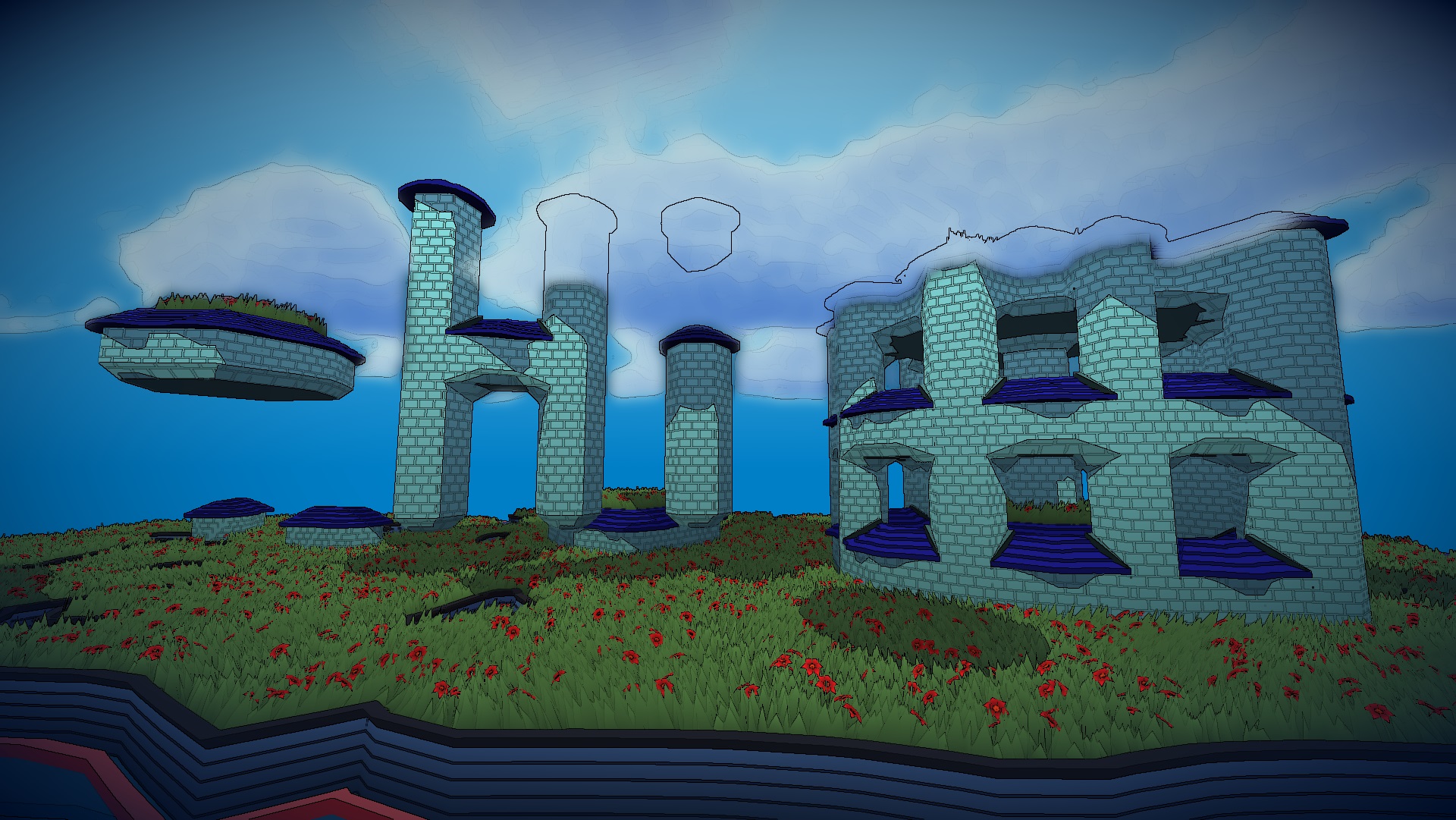
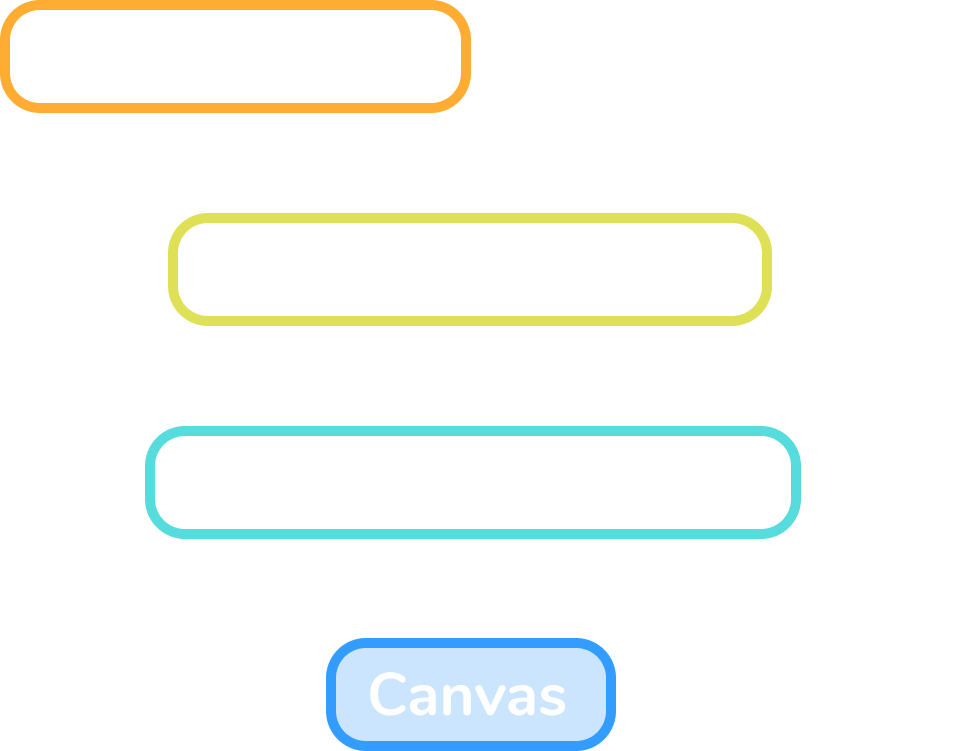
Mesh Generation
The scene has only 6 Three.Mesh objects in it.
1
The entire tower structure is a single mesh. When the marching
triangular prisms algorithm is executed a new position and uv
buffer is generated that contains the new models. This is done
by transforming the previously cached barycentric positions into
cartesian coordinates using the vertices of the triangle
defining each prism.
2
The reflection is the same mesh as the tower structure, but with the y component of the scale set to -1.
3-4
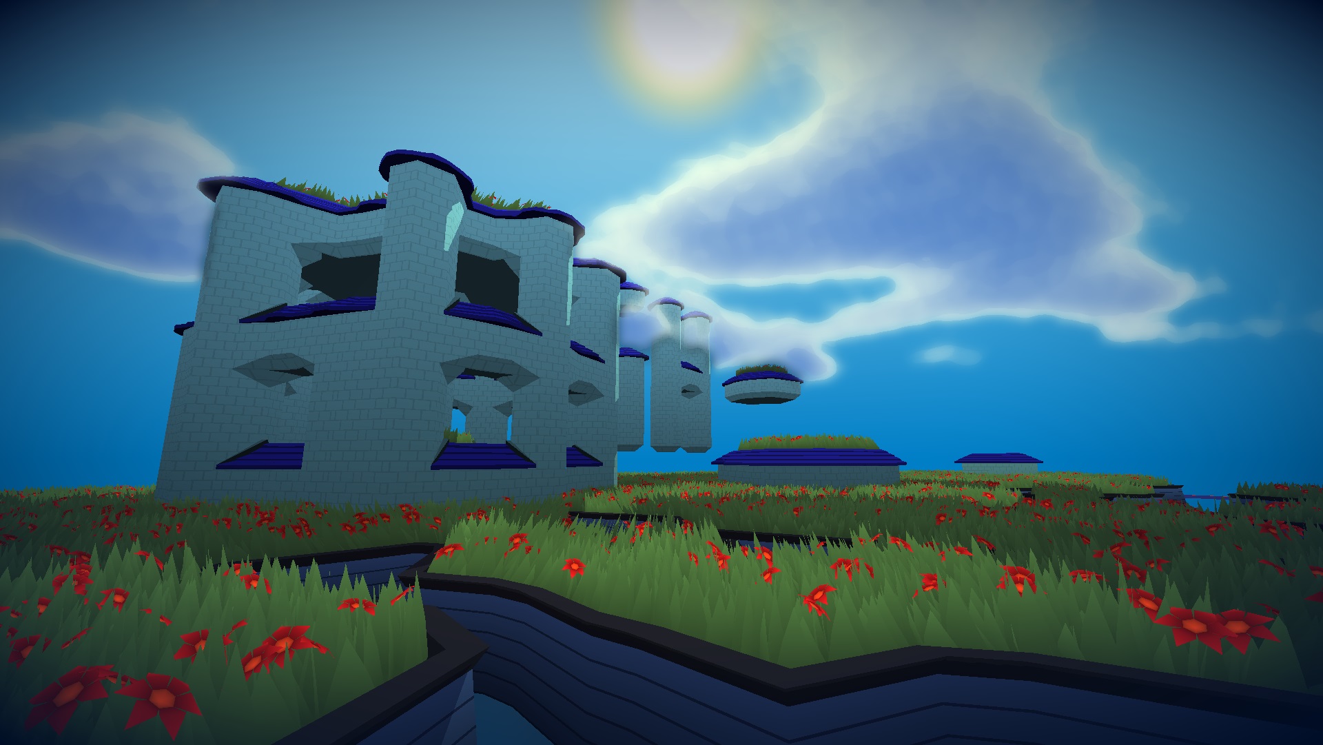
The Grass and Flowers are 2 instanced meshes and their positions are computed using the previously cached grass triangles. To place them I create a grid of points over the triangle, place a point on the center of each cell, and compute a random movement vector to offset its position a bit, if the resulting point is inside the triangle then place a blade of grass or a flower there (choosen randomly).
5
The water plane which is only used to show the shadows that would fall on the water.
6
A sphere that is front side culled that is used to render the background.
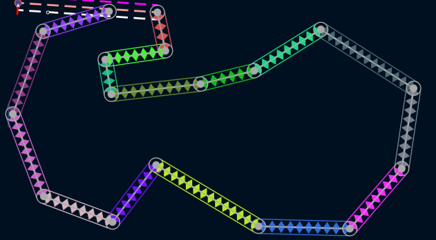
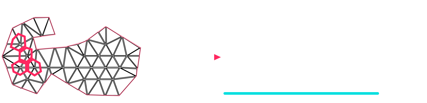
Scene Raycast
Arguably the most important part of the system, the raycast from the
current mouse position into the 3d. In my system the raycast is done
via a custom ray casting algorithm that raycasts into the prisms
that represent the shell of the different vertices. The pink
outlines represent the shell of each vertex, and it is made
connecting the centers of the triangles connected to the vertex.
Only the inner vertices are taken into account in the ray casting
process.
The raycasting system uses the camera position and a 3d vector created from the current mouse position. The system does 2 raycasts per Vert layer starting from the nearest vertex layer down:
1
3d raycast on a plane with normal (0,1,0) and position (0,vLayer + 0.5,0), if the ray hit, take the xz components of the hit and check if the position is inside the 2d shell of any of the vertices on that layer (only the vertices with the current state set to ‘tower’ are checked), if it is inside one, return that vertex index as the hit.
2
If no ray is found on the previous step, then a 2d raycast is performed using the xz components of the mouse ray and the edges of the shells of the vertices in the current vertex layer. From the shells, the only edges that are considerd “valid” are the ones that are the boundary between a ‘tower’ and ‘air’ or ‘tower’ and ‘water’ vertices. If there was a hit, then an extra computation is performed to check if the ray would have hit that face of the prism in 3d space, if it would have then it is added to a list of possible hits. After this process is done for every vertex in the layer, if the list is not empty the closest is chosen as the valid hit.
3
If the current layer is the water layer (vertex layer 0), then the same process as step 1 is done, but this time the plane position is (0,0,0) and the vertices with state set to ‘water’ are also checked.
4
If the previous steps return nothing then the process is done with the next vertex layer down until the layer 0 (water layer).
If the hit was registered on
step 1
, then the state of the vertex on the vLayer + 1 is changed; if the
hit was registered on
step 2
, then the state of the adjacent vertex is changed; if the hit was
registered on
step 3
, then the vertex that was hit changes state. The state change
depends on the action, if it is “add”, it is changed into the
‘tower’ state, if it is “remove” then it changes to ‘air’ if the
vertex layer is greater than 0 and changes to ‘water’ if the vertex
layer is equal to 0.
NOTE
: The outer vertices are not used on the raycast, they stay as their
initial state. This is done to ensure the marching prisms algorithm
always generates a closed shape.
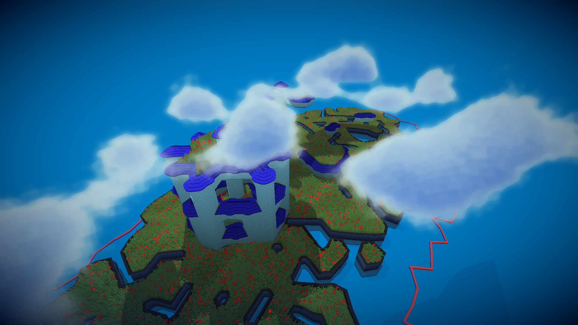
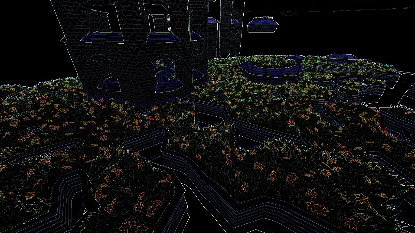
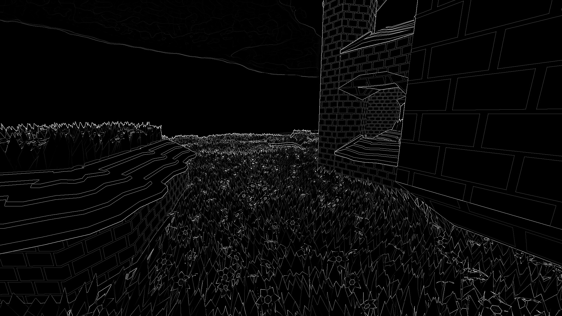
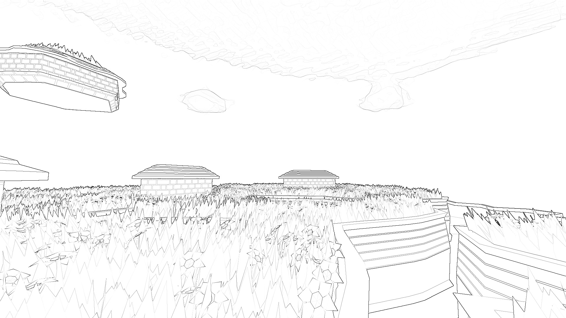
Render Process
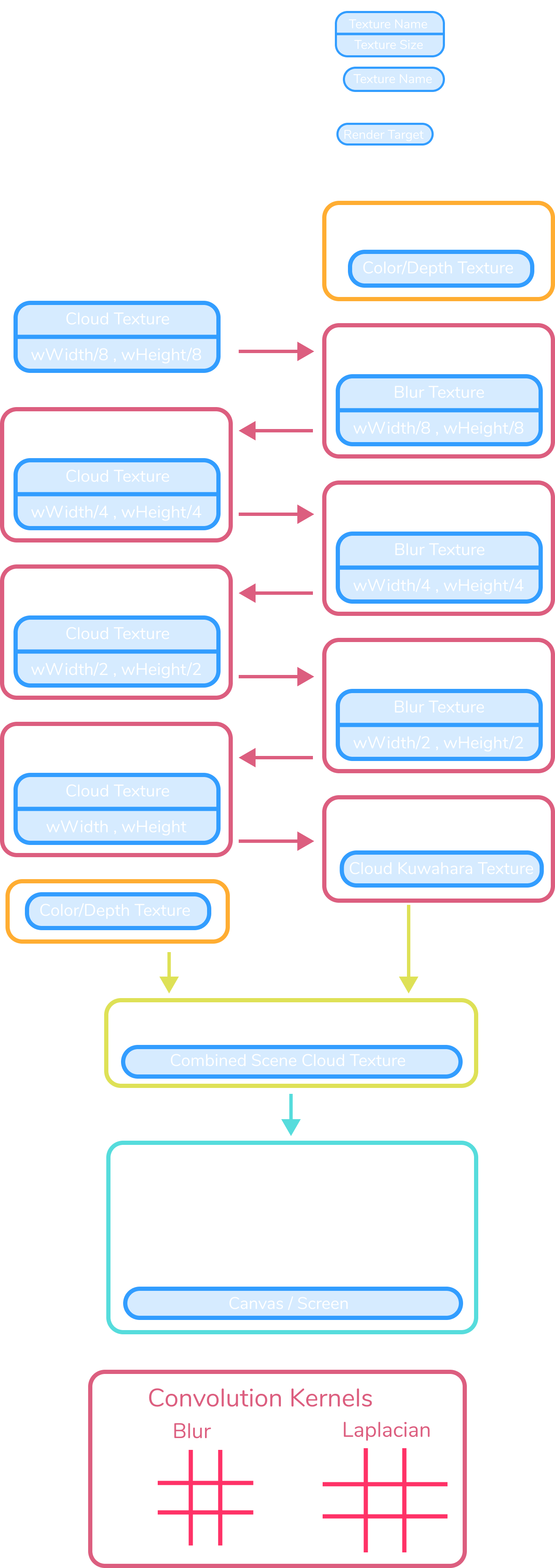
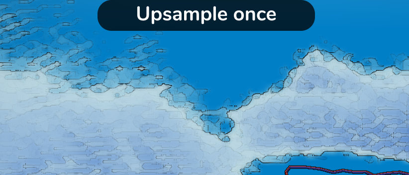
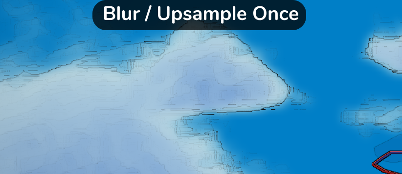
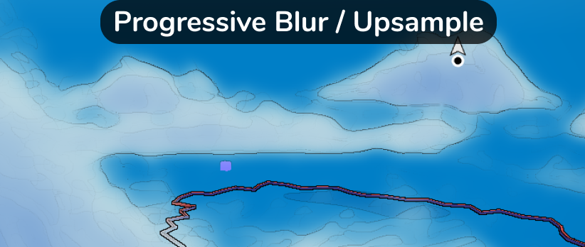
Progressive Upsample
The progressive upsample and blur passes produce a much smoother
result than directly upsampling the cloud texture.
- After one blur and upsample pass the clouds are less noisy and the
color gradient is more moderate, resulting in fewer aliased edges.
- After several passes larger clouds with gradual contours appear,
resulting in continuous outlines.
The cloud renderer uses a smaller render target than the screen
resolution to improve performance.