Euri Gilberto Herasme Cuevas
Euri Gilberto Herasme Cuevas
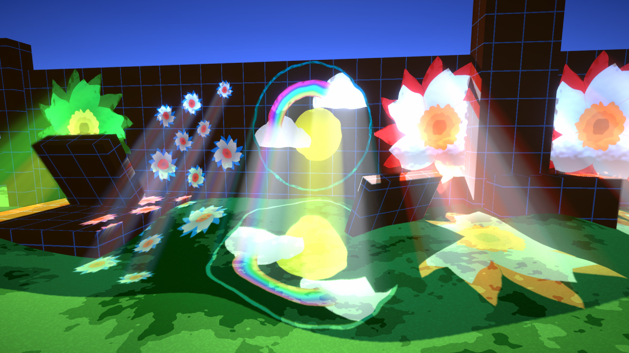
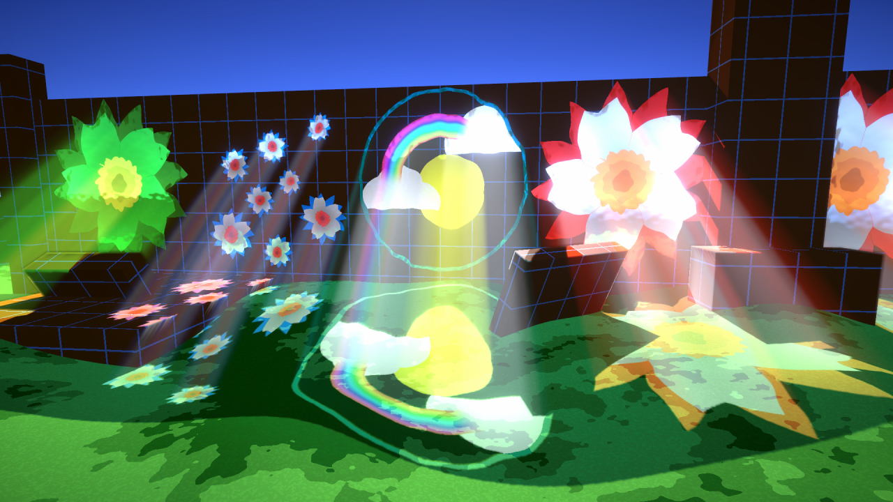
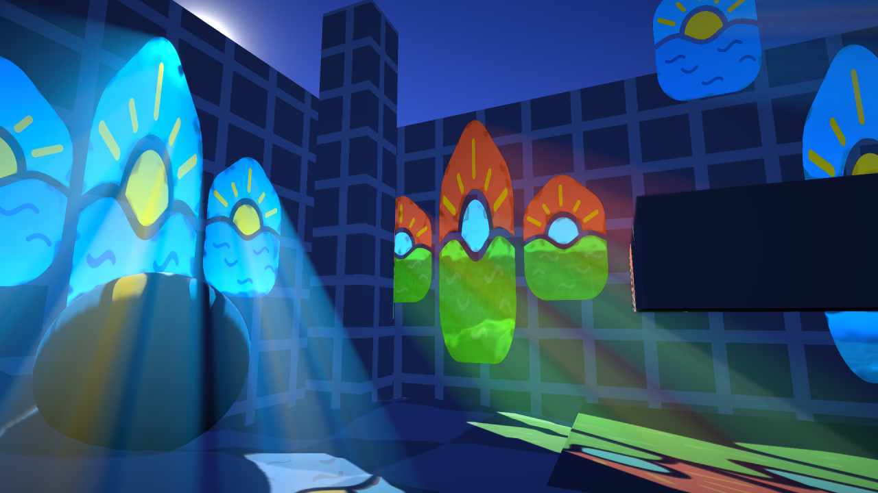
Volumetric Light Shaft
This is a recreation of the awesome stained glass light shafts @Cyanilux made for @HarryAlisavakis #TechnicallyAChallenge (theme: stained glass ). It was made with Unity - URP using a render feature.
Unity
HLSL
URP
Scriptable Render Feature
C#
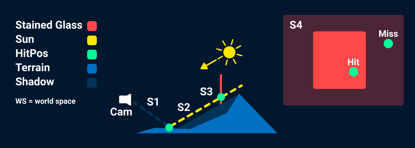
Step 1
Create WS position form depth texture.
PosWS = CamPosWS + ViewDirWS * EyeDepth;
There is a code snippet below that shows how to calculate the
View Direction and Eye Depth.
Step 1.5
Sample shadow texture to see if that point would be occluded by a shadow.
Step 2
Cast a ray using “PosWS” as the ray origin and -SunDir as the ray direction.
Step 3
Check if the ray intersects the plane.
Step 4
If it intersected the plane, check if the ray hit where our
texture is mapped.
This can be done by creating a vector that sits on the plane:
HitPosPlane = HitPosWs - PlaneCenter;
Then using a tangent and bitangent to our plane
float
textureU =
dot
(HitPosPlane, tan) / (tanLength * tanLength);
float
textureV =
dot
(HitPosPlane, btan) / (btanLength * btanLength);
float2
planeUV =
float2
(textureU + 0.5, textureV + 0.5);
float2
absPlaneUV =
abs
(planeUV);
bool
planeIntersected = (absPlaneUV.x <= (0.5)) && (absPlaneUV.y <=
(0.5));
On unity you can calculate all the required vectors using:
var
tMatrix = gameObject.transform.localToWorldMatrix
Vector3
tangent = tMatrix.MultiplyVector(Vector3.right);
Vector3
normal = tMatrix.MultiplyVector(Vector3.forward);
Vector3
bitangent = tMatrix.MultiplyVector(Vector3.up);
This asumes that your plane faces the local Z axis of the object
and that the Quad used to render the stained glass texture is
has side lengths of 1 and the aspect ratio is corrected by
scaling the object.
sampler2D _CameraDepthTexture;

struct StainedGlass{
    float3 planeNormal;
    float3 planeTangent;
    float3 planeBitangent;
    float3 planePosition;
    int textureIndex;
};

struct PlaneInterData{
    float3 intersectionPosition;
    float2 textureUV;
    bool intersection;
};

PlaneInterData PlaneIntersectionData(StainedGlass stainedGlass, float3 rayOrigin, float3 rayDir){
    PlaneInterData intersectionData;

    intersectionData.intersection = false;
    float denom = dot(stainedGlass.planeNormal, rayDir);
    if (abs(denom) > 0.0000001) {//it needs to be absolute value because the light vector could be oposite to the plane normal
        float3 p0l0 = stainedGlass.planePosition - rayOrigin;
        float t = dot(p0l0, stainedGlass.planeNormal);
        t = t / denom;
        if(t >= 0){
            intersectionData.intersectionPosition = rayOrigin + rayDir * t;
            float3 planeVector = intersectionData.intersectionPosition - stainedGlass.planePosition;

            float tangentLength = length(stainedGlass.planeTangent);
            float bitangentLength = length(stainedGlass.planeBitangent);

            float textureU = dot(planeVector, stainedGlass.planeTangent) / (tangentLength * tangentLength);
            float textureV = dot(planeVector, stainedGlass.planeBitangent) / (bitangentLength * bitangentLength);

            float2 planeUV = float2(textureU, textureV);

            float2 absPlaneUV = abs(planeUV);
            intersectionData.intersection = (absPlaneUV.x <= (0.5)) && (absPlaneUV.y <= (0.5));
            planeUV += float2(0.5,0.5);
            intersectionData.textureUV = planeUV;
        }
        else{
            intersectionData.intersection = false;
        }
    }

    return intersectionData;
}

struct v2f
{
    float2 uv : TEXCOORD0;
    float4 vertex : SV_POSITION;

    float3 viewVector : TEXCOORD1; //required to pass the view vector to the pixel shader
};

v2f vert (appdata v)
{
    v2f o;
    //vertex shader things

    //The following calculation from the view vector was taken from Sebastian Cloud implementation https://github.com/SebLague/Clouds
    float3 viewVector = mul(unity_CameraInvProjection, float4(v.uv * 2 - 1, 0, -1));
    o.viewVector = mul(unity_CameraToWorld, float4(viewVector,0));

    return o;
}

float linearToEyeDepth(float z , float3 viewVector){ //From unity
    float divisor = _ZBufferParams.z * z + _ZBufferParams.w;
    float depth = 1.0/(divisor);
    depth *= length(viewVector);
    return depth;
}

float4 frag (v2f i) : SV_Target
{
    float depth = tex2D(_CameraDepthTexture, i.uv).r;
    float2 UV = i.uv;

    float eyeDepth = linearToEyeDepth(depth, i.viewVector.xyz);

    //Continue shader
}
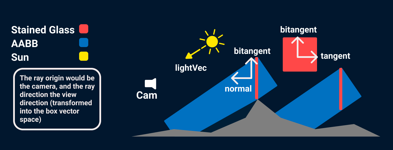
The first step to render the light shaft is to know if there are any
light shafts to render and where to start looking for them. This
step is important because ray marching is expensive, so the less we
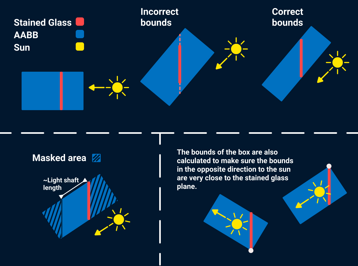
do it the better. The render regions are calculated by doing a ray
to AABB intersection test. The box is going to be aligned to the
axis generated from the light direction, and the stained glass' quad
tangent vector and bitangent vector.
float3
boxY =
cross
(lightVec, tangent);
float3
boxX =
cross
(bitangent, lightVec);
float3
boxZ = lightVec;
Remember not to normalize the plane vectors to make sure they retain
the scale information.
Information on how to get the tangent and normal vectors in the
previous section.
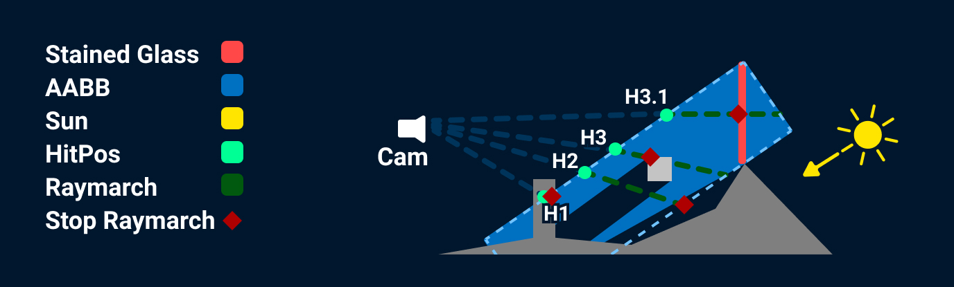
The previous image shows what happens to a ray after it is fired.
H1
The hit position in world space was at a distance from the camera greater than the scene depth distance, so the ray march is not started.
H2
The ray is not being occluded by anything, so the ray march is started, some of the light information is going to be attenuated by the shadow and the ray march stops at the limit of the box.
H3
The ray is not being occluded by anything, so the ray march is started, and the ray march stops early because the scene depth is reached.
H3.1
Same as H3 but stops early because the stained glass depth is reached (which in my implementation checks for every stained glass).
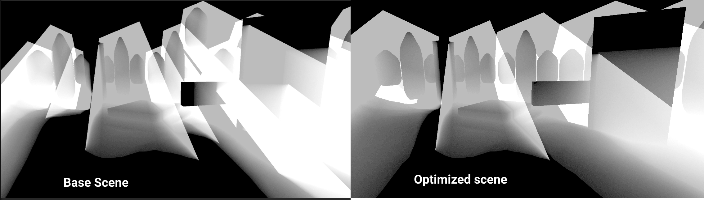
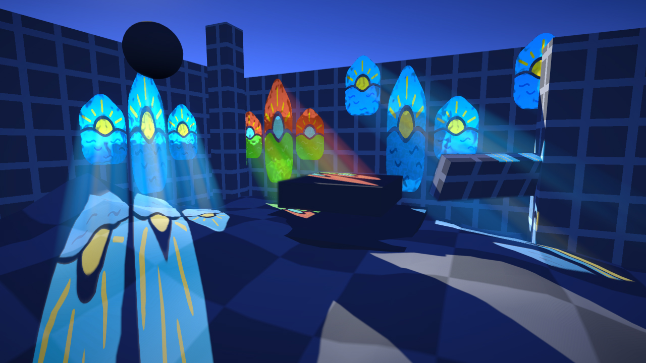
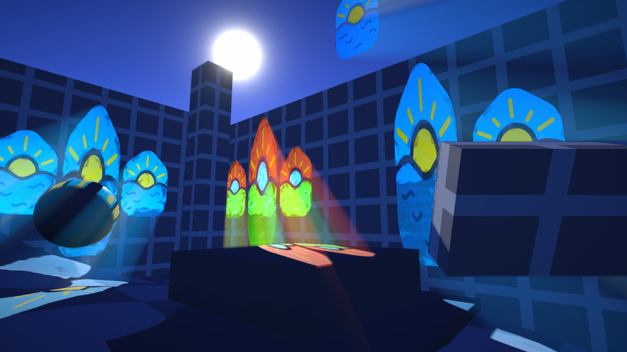
Another important thing I had to consider with this system is how the stained glasses were distributed. There is a limit to how many steps the system can take per light shaft (30 on the image), but there is no limit to how many light shafts a single ray can pass through. (The color in the image represents the amount of steps taken on that pixel, from 0 - 1 = 0 - 40 steps). On the “Base scene” image the windows on the sides have a stained glass object per window, on the “Optimized scene” image the windows are grouped in groups of 3, and it is apparent because of the reduction in illumination in the image. (On the “Optimized scene” there is a patch of white in the glass to the left, that is because there is a glass behind that one, it also appears on the other image but is less noticeable because that image has more steps overall).